안녕하세요? 이번에는 전면에 LCD ? LED 시계 나오는 곳을 활성화 시켜 보겠습니다.
이 부분은 CoreELEC 를 설치하면서 따로 별 생각이 없었는데요. 본래 있는게 없다보니 너무 불쌍해 보여 살려 보았습니다.
참고링크는 하기와 같으며, 하기 링크의 첨부 자료를 그대로 활용합니다.
https://github.com/arthur-liberman/vfd-configurations
바로 시작하겠습니다.
1. openVFD 애드온 설치
하기와 같이 설치합니다.
설정 --> 애드온 --> 애드온 저장소에서 설치하기 --> CoreELEC 애드온 --> 서비스


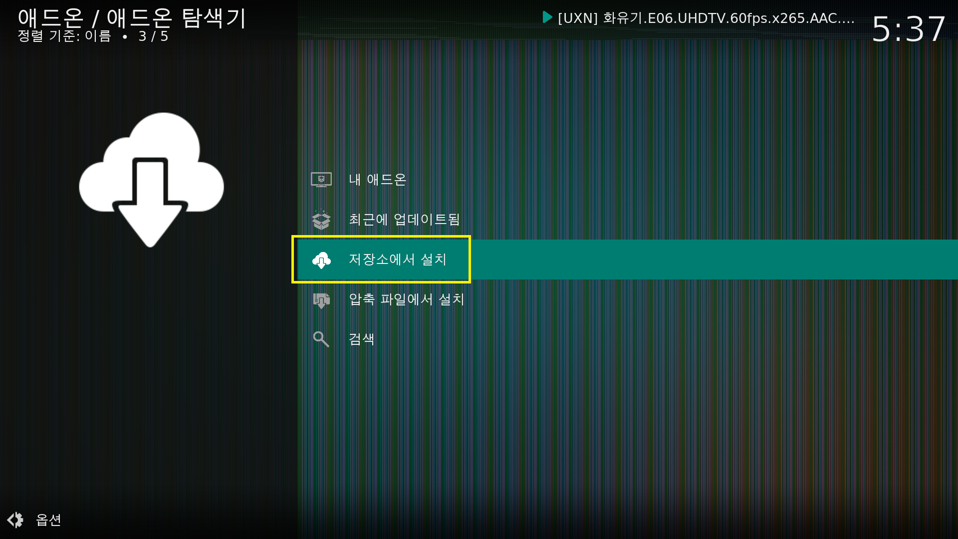


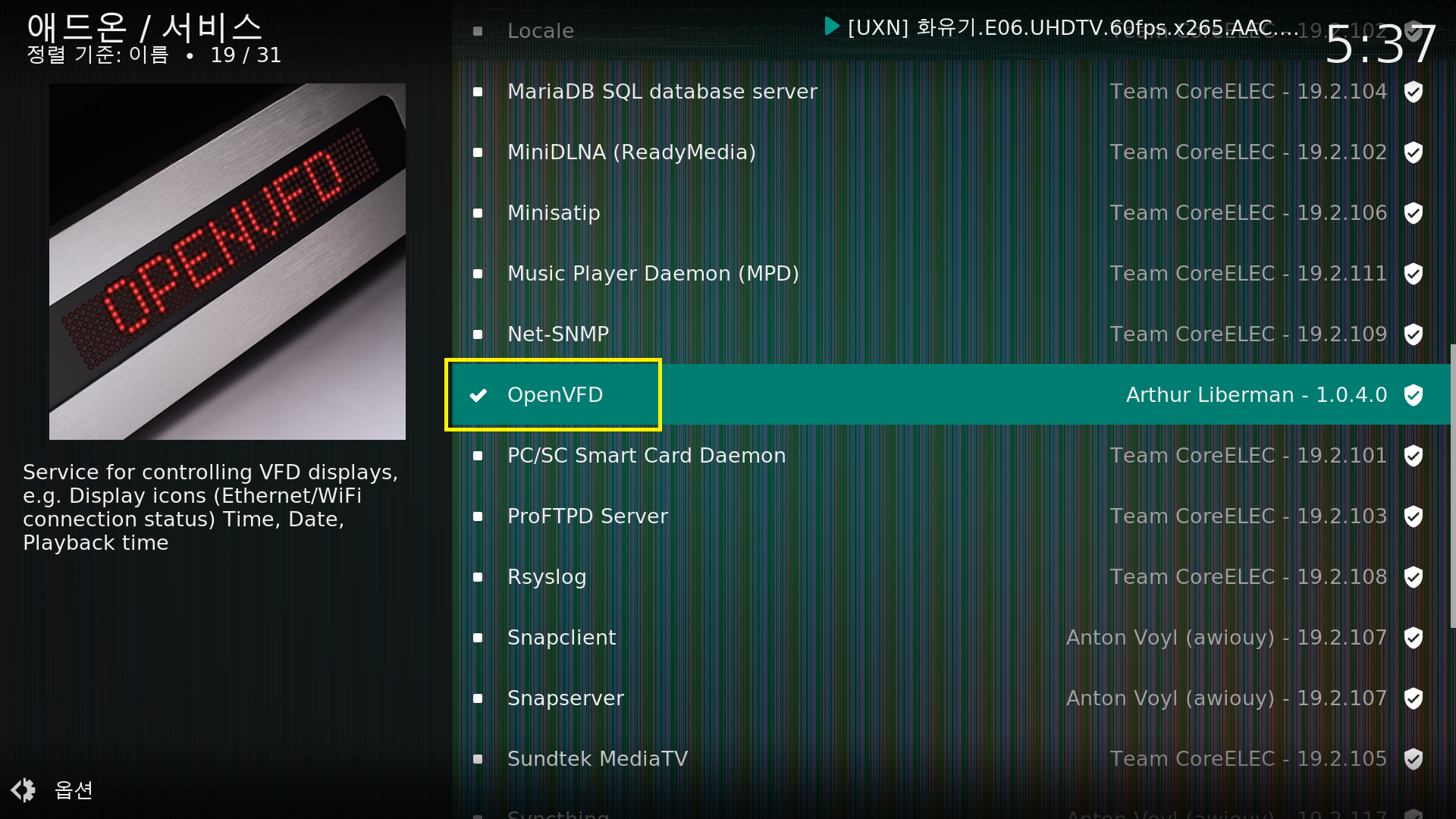
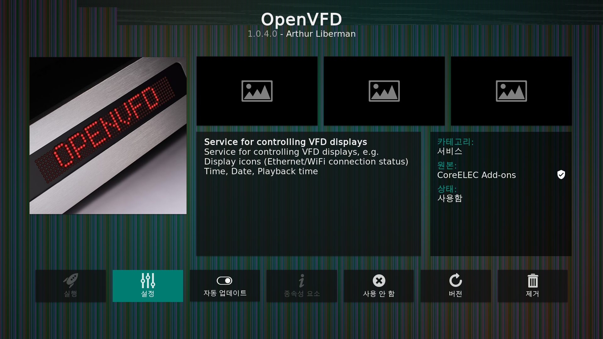
2. 애드온 설정파일 넣기
CoreELEC SSH 서버에 접근합니다.
혹은 전에 만들었던 Docker 컨테이너의 SSH 에 접근합니다.
| "System is booting up. See pam_nologin(8)" Welcome to Ubuntu 18.04.5 LTS (GNU/Linux 4.9.113 aarch64) * Documentation: https://help.ubuntu.com * Management: https://landscape.canonical.com * Support: https://ubuntu.com/advantage This system has been minimized by removing packages and content that are not required on a system that users do not log into. To restore this content, you can run the 'unminimize' command. Last login: Mon Aug 16 05:40:31 2021 from 192.168.0.8 root@CoreELEC:~# ceshell ############################################## # CoreELEC # # https://coreelec.org # ############################################## CoreELEC (official): 19.2-Matrix_rc3 (Amlogic-ng.arm) CoreELEC:~ # |
시작해보겠습니다.
| CoreELEC:~ # vi /storage/.config/vfd.conf # This file must be renamed to vfd.conf and placed in the /storage/.config/ folder. # # X96 Max (S905X2) configuration #-------------------- #gpio_xxx: # [0] 0 = &gpio, 1 = &gpio_ao. # [1] pin number - https://github.com/openSUSE/kernel/blob/master/include/dt-bindings/gpio/meson-g12a-gpio.h # [0] Reserved - must be 0. vfd_gpio_clk='0,65,0' vfd_gpio_dat='0,64,0' vfd_gpio_stb='1,10,0' #chars: # < DHHMM > Order of display chars (D=dots, represented by a single char) vfd_chars='4,0,1,2,3' #dot_bits: # Order of dot bits. Typical configurations: # Display Type 0, 1 usually has Alarm, USB, Play, Pause, Col, Ethernet, Wifi dots # Alarm = 0, USB = 1, Play = 2, Pause = 3, Col = 4, Eth = 5, Wifi = 6 # Display Type 2 usually has APPS, USB, SETUP, CARD, Col, HDMI, CVBS dots # APPS = 0, USB = 1, SETUP = 2, CARD = 3, Col = 4, HDMI = 5, CVBS = 6 # Display Type 3 Power, LAN, Col, Low Wifi, High Wifi # N/A = 0, N/A = 1, Power = 2, LAN = 3, Col = 4, Low Wifi = 5, High Wifi = 6 vfd_dot_bits='0,1,2,3,4,5,6' #display_type: # [0] - Display type. # [1] - Reserved - must be 0.. # [2] - Flags. (bit 0 = '1' - Common Anode display) # [3] - Controller. vfd_display_type='0x02,0x00,0x01,0x00' |
상기를 입력하고 저장하고 리부팅합니다.
| CoreELEC:~ # sync CoreELEC:~ # reboot |
3. 체킹 및 마치며
리부팅하면 정상적으로 LED 화면에 시간과 상태가 표시됩니다.
이 디스플레이 설정을 조금 수정해보려고 했으나, 본래 모습이 좋은 것 같아서 그냥 두기로 마음먹었습니다.
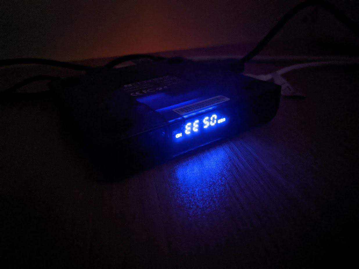
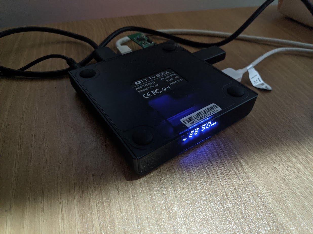

이 부품의 데이타쉬트는 하기와 같습니다.
https://pdf1.alldatasheet.com/datasheet-pdf/view/232882/PTC/PT6964.html
무언가 데이타 쉬트로는 SPI 를 사용하는 것처럼 되어 있네요.
드라이버 파일은 하기와 같습니다.
https://github.com/LibreELEC/linux_openvfd/blob/master/driver/openvfd_drv.c
상기 드라이버를 보면 misc_register 를 통해 /dev/openvfd 의 장치를 등록하는거 같은데요.
| root@CoreELEC:/dev# ls | grep openvfd openvfd |
있습니다.
ioctl 및 sysfs 인터페이스를 통해 밝기 조절등을 할 수 있는 것 같은데요. 실제로는 안되는 것 같습니다.
| root@CoreELEC:/sys/class/leds/openvfd# ls brightness led_cmd led_on power trigger device led_off max_brightness subsystem uevent |
코드를 살펴보아도, 밝기 부분관련해서는 코드가 구현되어 있지 않았습니다.
| static void openvfd_brightness_set(struct led_classdev *cdev, enum led_brightness brightness) { pr_info("brightness = %d\n", brightness); if(pdata == NULL) return; } |
대략적으로 이 부분이 어떻게 돌아가는지 알아보았습니다.
간단하게 마치겠습니다.
감사합니다.
'컴퓨터.전자기기' 카테고리의 다른 글
| 라이젠 5600X 조립기 (390) | 2021.10.19 |
|---|---|
| 크롬 브라우저 저사양 최적화 (램 사용량) (401) | 2021.10.03 |
| QCY T13 사용 후기 (통화품질 : ★★★☆☆ / 음질 : ★★★★☆) (2) | 2021.08.12 |
| X96 Air P4 / EMMC 에 CoreELEC 설치하기 (0) | 2021.08.12 |
| X96 AirP4 간단 리뷰 및 Coreelec 설치하기 (0) | 2021.08.02 |


댓글